Happy with my first SSB QSO via QO-100 Satellite with VO100QO.
Grid was GN37pl south of St.John's Newfoundland Canada. (Abt 11400 Km from St Helena Bay South Africa grid JF87XF)
link here: https://www.qrz.com/db/VO100QO


Happy with my first SSB QSO via QO-100 Satellite with VO100QO.
Grid was GN37pl south of St.John's Newfoundland Canada. (Abt 11400 Km from St Helena Bay South Africa grid JF87XF)
link here: https://www.qrz.com/db/VO100QO

FINALLY I GOT IT ! Award # 9 for150 Countries on QO-100 SAT


HamSat-SA ZS QO-100 QSO Party
The South African Radio League - Die Suid-Afrikaanse Radioliga
2023 SARL Contest

The HamSat-SA ZS QO-100 QSO Party
1. Aim:
This is a fun activity to promote contacts between radio amateurs from South Africa and the
world using the QO-100 satellite. The aim for stations from ZS to as many different countries
as possible.
2. Date and Time:
From 14:00 to 15:00 UTC on Sunday 12 February 2023
Duration too short, but happy, I received the certificate to the 1st place.

Total countries today


Results: output = +24 dB 1nd LNA 1st attenuator of 6 dB has the input removed.
Installation of 2 Gali-5-05 on the 2nd LNA (2 attenuators removed) Measurements by injecting a 1296 Mhz signal at 0dB.
Result: output = +30 dB.
These 2 LNAs will be used for: an noise signal meter for the EME.

A CW QSO archive recorded by JA0RUG in 2009 on 28 Mhz with my call 9Q1EK
'' Click on the link below''

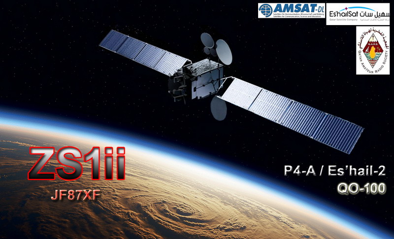
Some nice QSO on geostationary satellite Es'hail-2, QO-100, more will follow..
DXCC = 147 countries - 03 July 2019 to 21 March 2023


03 July 2019 to 21 March 2023
SSB/CW/DATV
DXCC = 147 countries

TNX to all





Version 2016-03-06 Named ''Nose source''.
The PCB circuit received is clean and of good quality.
I will not go back over the various opinions, tests, modifications already made in the past. I'll just experiment with a new approach to modify it.
Because there is a heat problem which seems to be a recurring one with this noise source.
After a short amount of time, I can see this heat problem., The three amplifier semiconductor packages and resistors become very hot and will have a limited life span due to excessive heat.
** And more
• Don't like 24V Zener diode powered by the MC34063A (despite R11 to limit the voltage)
• Don't like MMIC's powered by 12Vdc unregulated (despite R8 / 9/10 to limit the voltage which can vary at the input).
• Output noise of the Zener source is very high
• Output after three stages of MMIC too high.
• Power density of noise is not flat towards high frequencies.
• MC34063A output is not as well filtered
• 12V DC input is not regulated.
• Then, some modifications will be made for tests.
- Powered in 12 VDC with New system on 5 Vdc power supply (regulator 5V) for MMIC'S (5v) and new zener diode.
- Input DC connector removed
- I don't use the converter 12 / 38v MC34063A (output is not as well filtered).
- L2 removed
- Zener diode replacement by a 5V and also tests with a BFR34A / BFR93 transistor
- New DC power supply with 7805 TO-220 for 3 X MMIC SBB5089Z = +5 V and zener diode.
- Addition of 10dB attenuator on output. (replacing of the 3 DB)
- R11 must be adjusted value 1 to 3k (depending diode/RF transistor).
- Installed in metal case.
- Waiting for SMD Ferrite Bead inductor to replace L3/L4/L5
The diagram below is worth less words… !!!
1st remark: At 1.5 Ghz, the curve is flatter, but the signal at higher frequencies decreases slightly. Still very usable for the quality and low price for an amateur.
(Later, some pics and probably other experiments ....)
** Update 11/09/2021
Even being in a metal case, there are self-oscillations, especially around 2.4 GHz !! it's embarassing for the WI-FI or 13cm band.
To dampen the oscillations or try to eliminate them, I added above the PCB, under the metal cover and on the 4 sides, an RF EMI ABSORBING SHEET.
The noise spectrum is even flatter and elimination of oscillations towards 2.4 Ghz.
I also replaced the L3 / L4 / L5 chokes with SMD Ferrite Bead inductors.
There is still too much signal even after changing the attenuator from 3 to 10 dB.
Before trying to remove the last MMIC, I added a 10dB on the SMA output.
(Original Schematic is from Alyx, Dodgy Engineering Rockville, MD)

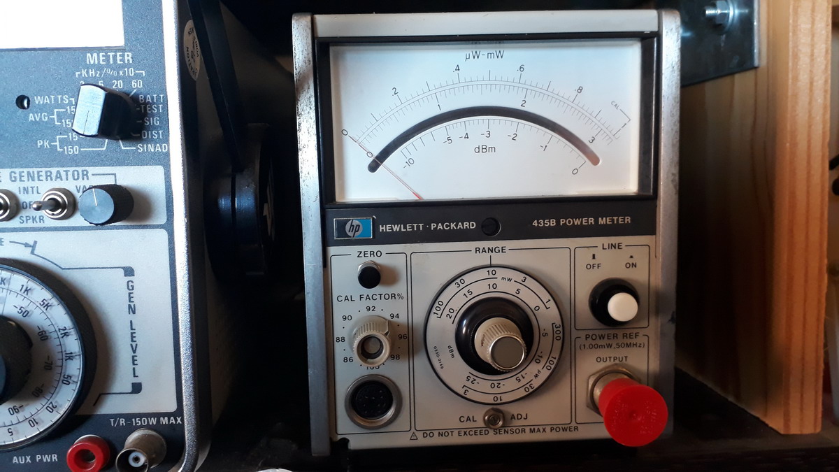
Some essentials accessories have entered in the lab after good auctions. Used but with Calibrated Certificate.
Now, enough equipment (Maybe !!!!) for my measurements.
Wattmeter Slugs - HP437B - Sensors: HP 8484A HP8482H - HP 435B + Accy's

 |  |
 |  |
 |  |
I have a NMRF 2450MHz Band-pass Filter Central frequency: 2450 MHz for WiFi.
and I found loss:
2.400 Ghz = 5.2dB , 2.409 Ghz = 4.7dB.

I have also couple of WI-FI around me near 2.450 Ghz and this BPF is is not effective..
So I'm not satisfied with the BPF NMRF 2450, I tried to made a new one on 2,4 Ghz for QO-100.
Several months ago I built 23cm Inter digital filter for 1296.2Mhz with succes (0,85dB loss)
But with my homemade new 13cm BPF, I have about 2.7dB Loss between 2.400 to 2.409. Not really satisfied again, I have to start experimenting again.
(Inspired by DD1US, DL3NQ and VK3UM Inter Digital Filter Design)

 1 |  |
The dish suffering, it needs repairs and reinforcement after the lull.
 |  |  |
Today, Repairing. Use of large washers and galvanized wire ties. It seems to be solid! we'll see next time!
 |  |
I took the opportunity to check that the feed Poty / LNB are in the axis and in the center of the dish. Results, Hey No, not on the center. So I use the old method used many years ago. A pipe installed and blocked on the feed attachment. Perfect now! Next Wednesday, re-installation of the dish.
 |  |  |
Gain and Beamwitdh of my prime focus


Some countries contacted in CW/SSB from May 2019 to August 2021
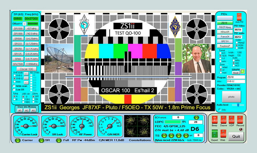
------------1St Test on QO-100 DATV ---------------------------
Equipment:
- DC Power supply 12/28v
- Up converter, Adalm Pluto modified
- RF power amplifier with Output 35/60w, ready.(AMPLEON BLC2425M10LS250)
- DATV receiver Minitioune V2 - OBS F5OEO
- 1,8m prime focus dish for TX. with Poty
- 80 cm offset dish for RX with Down Converter Khune.

