CUSHCRAFT - R7000 Prob and repair.
Hi Folks,
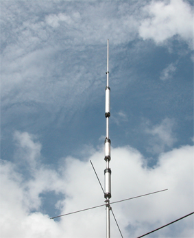
Not lucky with the first installation of Cuschraft R7000 in 9Q1 (Rep. Dem. of Congo)
After having received from Switzerland a second hand antenna Cuschraft R7000, I installed it but only the 18 MHz was operational.
I decided to see what happened with that while disassembling this antenna completely.
Remarks:
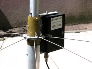
- The screws of fixings for all coils on the capacitor tubes were loosen.
- has the inside of the coils, two had a great deal of bites, spiders, etc amalgamated in the base of the coils.
- Big humidity inside the coil.
- Coil of 14 and 10 MHz burnt. (Due, no doubt about that for an elevated VSWR and a short circuit probably with the water, accumulated bites and nests of spiders)
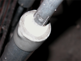
- Internal capacity in the coil of the 21 MHz (small aluminum pipe in serial on the coil and isolated by Teflon) completely loosen, and electrical sparks, (rivet “pop” was deficient, no contact)
- The insulating part has the basis of the antenna (fiberglass) damaged behaving like a sponge.
- Water also goes back on the top of every pipe between the coils.
Repair and method used:
- disassemble every coil carefully.
- remove all screws and move carefully the alu. small loop of every coil inside the capacity trap.
- With a nylon hammer hit slightly on the tube dia. abt 2cm to remove them of the capacitor pipe.
it only holds by two struck points in the capacitor trap on the middle of the trap.
- clean correctly each coils, and every insulating PVC support of the coils.
- I removed the burnt plastic part of every coil PVC and added of the insulating joint in the cleaned holes. (Like same procedure with the dentist... hi)
- apply 2 layers of varnish to all coils.
- make a new small hole like 4 mm dia near the PVC to suppress the fixing with the screws for the coils.
Move the spire of the coil above the new hole that you made and fix it with aluminum. Rivets “pop”


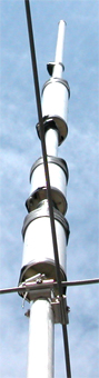
- Put back the insulating joint on the top of the 3 trap protections rubber.
- add a sufficient quantity of amalgaming tape over it.
Every screw of fixing of the coils was blocked with nails varnish and some amalgaming tape has been added.
I put 3 layers of varnish on the insulating part in fiberglass (bottom of the antenna)
* The first measures were extremely interesting.
A very and constant big dip on all frequencies was observed on 7, 10, 14, 18, 21, 24, 28 Mhz with MFJ-259B analyzer.
 I think that after these modifications, I will be quite for several years.
 73 Georges VE2EK - 9Q1EK - ZS1II